Colin's ring walkthrough
This Modela Player 4 ring walkthrough is presented by kind permission of Colin Creed, an experienced Fourth Axis user.
Before you start:
- Ensure you have calibrated the best Y-setback position for your Fourth Axis unit,
- ensure you have calibrated the best Z-zero height for your unit,
- ensure you have entered your rotary unit's Calibration Number into FARM,
- ensure you have installed the latest version of FARM and Modela Player 4.
What you will need:
- 1 x 1/8 inch (3.175mm) two-flute endmill,
- 1 x 1/40 inch (0.635mm) two-flute endmill (with a minimum reach of 2.75mm),
- a Fourth Axis cone clamp attachment,
- a machinable wax tube.
An MDX-15 fited with a standard Roland motor with the 1/8 inch spindle collet was used for this tutorial. The majority of micro cutters are made in the USA, and most of them will have a 1/8 inch shaft size and will be measured in inch increments.
I can buy most of my cutters from Bits & Bits.
I set up Modela Player 4 (MP4) with the "Machine selection" set to a JWX-10 with the standard rotary.

Register these settings for the 3.175mm endmill.
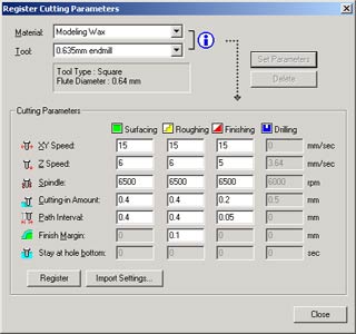
Register these settings for the 0.635mm endmill.
I have supplied the STL file for this model already oriented in the correct position for machining on the Fourth Axis rotary. The model has been designed with supporting bridges included.
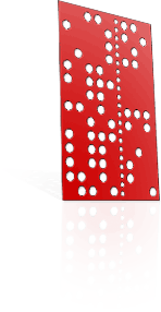
For this model I used a standard wax tube that measures 1 1/16 inch (27mm) outside diameter with a 5/8 inch (15.9mm) inside diameter, purple in colour. I always size the wax first; in this case, the model is designed for "British Size P", or "US Size 7 1/2", or 18mm inside diameter.
Once the wax is correctly sized, I cut the wax to a suitable length to fit the model and allow for the margins to support the model. This model is 14mm in length and requires 2mm margins on each side, so the wax was cut to a length of 18mm.
The cone clamps will grip the 2mm margins on each side and allow the small endmill to cut the sides of the model without hitting the cone clamps.
I measure the thickness of the wax to find its thickest point; this will then give you a maximum value for the surfacing start height in MP4 -- in my case the wax was 4.95mm thick.
I then mark the centreline of the wax tube; in this case half of 18mm = 9mm. This centreline will be used to align the endmill when setting up the wax position within FARM.
Install the wax into the cone clamp attachment and check that the wax is secured and won't move. The wax only needs to be held firmly, not crushed, between the cones.
Now fit the 1/8 inch (3.175mm) endmill in preparation for aligning the wax in FARM and executing the surfacing toolpath.
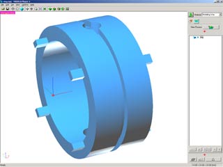
Open MP4, and make sure that "Modeling Wax" is the selected "Material" from the control panel drop down list. Now open the ring.stl file. It will appear in wireframe form. Click the "Rendering" button from the toolbar.
The model now appears as a rendered blue ring showing all the surfaces and details of the design.
Look to the control panel on the right-hand side of the MP4 screen. We will use the functions to set the model position and generate the toolpaths needed.
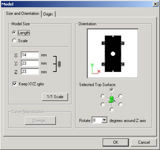
Click on the "Model" button to show the model's size and orientation. We will leave these settings as they are.
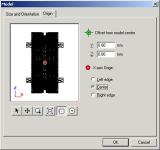
Click on the "Origin" tab. Set the model origin to the "Centre" position and click "OK".
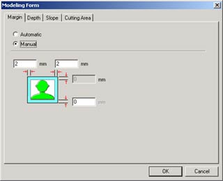
Click on the "Modeling Form" button to set the margins and depth.
The margins for this model need to be 2mm for both the left and right sides.
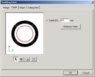
Click on the "Depth" tab, and note the settings. In the case of this ring, we do not want the tool to make any attempt to cut/where the shaft for the cone clamps exists.
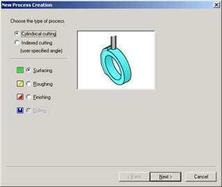
Click the "new process" button to start creating the first toolpath which will be "Surfacing". I do a surfacing pass to allow clearance for the smaller endmill which wouldn't otherwise have enough reach. Select "Surfacing" and click "Next".
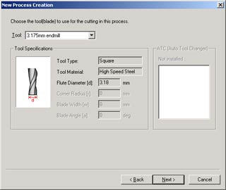
Now you can select the 1/8 inch (3.175mm) endmill you registered earlier. Click "Next".
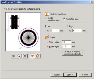
I select the "Specified Area" button and inspect both views of the ring.
Because the finger size of the ring is 18mm inside-diameter, we divide that by two to get 9mm [the distance from the centre], and add 4.95mm [the maximum thickness of the ring].
This gives us 13.95mm, which I round up to 14mm, and set as the "Start Height".
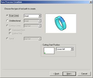
In this case, I don't need to alter the scanline settings, so I click "Next".
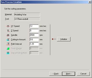
MP4 will now present you with the cutting parameters registered for "Surfacing" for "Modeling Wax" for your "3.175mm endmill" tool. These settings are fine, and I won't override them; click "Next".
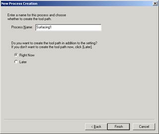
For now I leave the process name as its default "Surfacing1". Since I want to create and see the toolpath (because we will be exporting them to FARM), I choose to create a toolpath "Right Now". Click "Finish".
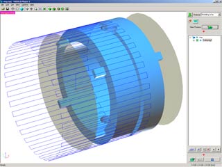
MP4 will now show the generated "Surfacing1" toolpath.
Continue onto the next "New Process" and create a pass for "Roughing". The process is almost exactly the same as before; select the 1/40 inch (0.635mm) endmill and click "Next" to move to the "Cutting Area" section.
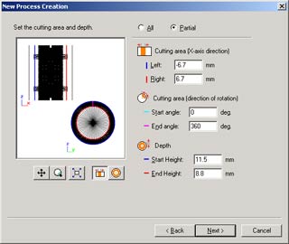
Here you'll need to select "Partial" cutting area and depth, and make the "Left" area -6.7mm and the "Right" area +6.7mm. This moves the cutting area between the support bridges, which will keep the model attached to the margins!
Set the "Depth End Height" to 8.8mm (because it is unnecessary to machine below where I have bored the inside of the tube, or where there is already empty space).
Note these dimensions as you will need to use them again when creating the "Finishing" process.
Continue on to complete the "Roughing" toolpath, and start a new process for your "Finishing" toolpath in the same way. Ensure to the same dimensions in "Finishing" as you did in "Roughing".
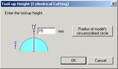
Once the "Finishing" toolpath has been generated, you can output all the cutting files for use in FARM. Click the "Cut" button at the very bottom of the control panel, and this will present the "Tool-up height" box.
Enter 15mm as this will give a 1mm clearance above the wax when the "Surfacing" toolpath starts.
Be careful with any calculations you do which may relate to the tool-up height. The MDX does not have collision detection!
Now we're close to milling! Start FARM, and follow on to the next tutorial: FARM operation walkthrough.