Correctly representing XYZ data as rotary data in Rhino3D
Dr Picza can only represent XYZ data, because it thinks it's scanning XYZ surfaces.
None of the data is 'lost' when you view it as an XYZ surface, it is just misrepresented.
Rhino won't recognize Picza's exported data as rotary data of its own accord. This is why we cover the use of the FLOW command to re-present scanned data for viewing, editing, and machining, as correct rotary data.
Important philosophy behind XYZ > Rotary data conversion:
Essentially, to correctly represent the XYZ data you save from Dr Picza as rotary data, it must be stretched 360 degrees around a circle. There are a few different possible ways to do this, depending on what you have scanned.
Scanning a real object...
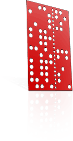
Let's start with this example object; an unembellished, simple ring, which has a varying semicircular profile along its circumference. Let's say the INSIDE RADIUS is 10mm, and the most prominent part of the ring extends 8mm above this inside radius.
We can scan this one of three ways:
- Scan only down to where we believe useful detail stops existing (a 'Z-bottom' 10mm above the axis of rotation)
- Scan down to the centreline (the 'Z-bottom' specified as equal to the height of the axis of rotation above the baseplate of the machine)
- Scan THROUGH and below the centreline to where we believe the useful detail ends (a 'Z-bottom' 18mm below the axis of rotation)
The third option encompasses "full diametral penetration" and will be the subject of a further article.
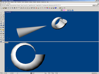
IF we scan only down to the inside radius: (1)
We can infer visually that we have captured all useful detail, as anything deeper involves scanning air or inaccessible undercuts.
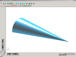
The geometric result of the scan will be half of a cone, lying flat on the plane Z=0
We must understand that Dr Picza does NOT know the data should contain 10mm of empty space under it. More on this later
IF we scan down to the axis of rotation: (2)
The data contains bogus solid information, namely the "cliffs" or "drapes" that extend to the centreline.
In Rhino3D, we will have to remove the superfluous solid data after the scan is correctly re-presented as rotary data, like coring an apple.
We must understand that this 10mm high solid block is a misrepresentation of empty space.
Which of these scans will we choose?
In this isolated case, the more preferable of the two scans is the first one.
We can also infer visually that it would be preferable to mill this model from hollow tube, and we can then ignore the "cliffs" created in the second scan.
Using FLOW to correctly represent this XYZ data in Rhino:
The FLOW command in Rhino3D is used to "conform" the profile of one object to a different profile specified by a line or a shape.
How it works is to allow the user to draw a "spine" near/in the target object, and then specify an alternative "spine" to distort the object onto.
Each point on the object is relocated as appropriate, relative to its position on the old / new spines.
The FLOW procedure for scanning above the rotation axis:
Open or import the XYZ file into Rhino, as per our Pix-Rhino Conversion Tutorial.
- Draw a miniscule circle in the "RIGHT" or YZ plane, underneath the model. We suggest a radius of 0.001mm
- Use the FLOW command and SELECT the model in the YZ plane. NOTE FOR RHINO v4.0 USERS: THE 'STRETCH' PARAMETER MUST NOW BE ENABLED!
- Select LINE ('L' spacebar) and consider how the line must be equal in length to the bottom surface of the model, and positioned Nmm under the model, where N is the distance above the axis of rotation you specified as the "Z-bottom" (in this example, 10mm).
- Click to select the first point of the line, whch must be parallel to the leftmost edge of the model; i.e. 10mm under the bottom-leftmost corner of the model visible in the YZ plane.
- Click to select the second point of the line, which must be parallel to the rightmost edge of the model; i.e. 10mm under the bottom-rightmost corner of the model visible in the YZ plane.
- When prompted for the "new backbone curve", simply click on the miniscule circle to select it.
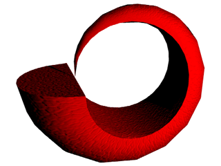
If you selected the length and position of the line correctly, then the model you see in Rhino will now correctly represent the data the rotary axis was able to capture in real life!
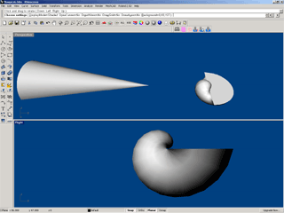
Watch out for this common mistake:
We reiterate that neither Dr Picza nor Rhino has any way of knowing that this XYZ data was supposed to be represented in a rotary fashion. Similarly, Dr Picza cannot export any data that tells Rhino that the bottom of the data captured is actually 10mm above: A) the base of the machine, or B) the axis of rotation, in this case.
For this reason alone, you must record the distance above the axis of rotation you specified as the "Z-bottom" in Picza. You can see this same dimension is used when you FLOW the object in Rhino.
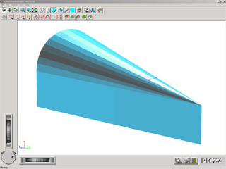
If, not realising that the bottom of the model does not correspond to the axis of rotation, you tell Rhino that it does, by drawing the first FLOW spine along the base of the model, the result will be distorted! See the image on the right.