Using the Z-height Adjustable Gauge
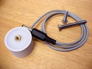
Your Fourth Axis® Model 15 and Model 20 rotary axis units are supplied with an LED indicating Z-height adjustable gauge, for very accurate tool length / height setting. It may be left connected at all times if you wish, because it uses no power unless the stainless setting screw is grounded through contact with a metallic cutter in the motor spindle.
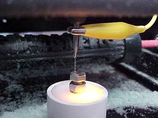
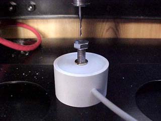
Pictured: The Z-Gauge illuminates to indicate the tool has contacted.
The alligator clip grounds the spindle, as explained in the very last
paragraph on this page.
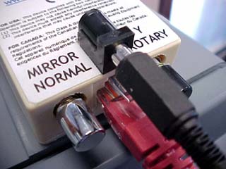
Locate the accessory power socket on the Fourth Axis® interface box. It's the black socket protruding from the label face of the interface box. Never insert anything but the plugs of Fourth Axis® tool setting accessories into this socket.
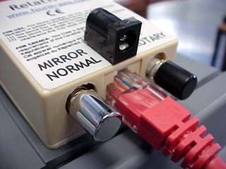
Insert the black power plug of the Z-height adjustable gauge into the Fourth Axis® accessory power socket. The grey Z-height adjustable gauge flexible lead is 600mm long, so you can route the lead anywhere convenient. Make sure there is no chance it will be caught in the rotating cutter, nor obstruct the safety screen.
There are two stainless steel adjusting screws supplied with the Z-height gauge. The shorter screw covers a height range of 25mm to 42mm above the base of the gauge. The longer screw extends the height range to 62mm above the base of the gauge.
This is where you will place the Z-height gauge -- on the metal XY motion table -- in a location you can conveniently touch with the cutter, using Fourth Axis® Rotary Machinist's handy 'Position Setup' page . The gauge base has 2 magnets.
FARM (Fourth Axis® Rotary Machinist) includes a "Position Setup" page which is more comprehensive than the page in Modela Player 4. We do recommend that you use the "Position Setup" page of FARM, or use our MDX Manual Machinist ("MMM") software, because it eliminates the spindle motor action when descending in Z. You don't want to CUT the gauge, you only want to gently CONTACT it!
Select the motion chunk size appropriate for approaching the gauge. From a distance you may use large chunks, say 10mm down to 1mm, but when you are close to the gauge, please select small chunk sizes, finally down to 0.025mm.
You can see the motion step selector window for Z, between the two yellow buttons. When moving the tool towards the gauge, always use our YELLOW BUTTONS on the screen. Do not use the UP/DOWN buttons on the MDX-15/20 because they start the spindle motor and do not allow progressive approach to the gauge.
Move the tool down with the YELLOW Z- button in 0.025mm chunks, until the tool tip just touches the gauge, pre-set with vernier caliper to the desired height. When contact is made, the bright yellow LED inside the gauge will light up. Now you can click NEXT in the FARM screen to set your Z zero value. Regardless of tool replacement or adjustment, the precision Z-height gauge allows you to obtain perfect Z-height, every time.
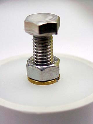
We provide a locking nut to allow permanent Z-heights to be gauged and set for batch runs or setups with jigs.
If you choose to use a third-party spindle such as a Proxxon motor, or a pneumatic spindle, we remind you that the spindle needs to be grounded for the Z-gauge to sense correctly. Ensuring that your spindle is turned OFF, connect an alligator-clip between the tool shaft and any exposed screwthread protruding from the chassis. We recommend connecting to the long brass thread accessible from the rear of your MDX-15 or MDX-20.