Tutorial using Tilt Motor Mount
Inside ring engraving using the Tilt Motor Mount
A real fast way to get into inside-ring engraving is with the free "Roland 3D Engrave" software provided with your MDX. Let's set up all the necessary settings first and guarantee you are working with the same version as this tutorial.
You will also want to have your Tilt Motor Mount installed in the LOW position, and, if you're working with a Proxxon 28481, a tool should be fitted for exploration of the appropriate angle (likely less than 30°).
We thoroughly recommend using metric millimeter units in Roland 3D Engrave. It looks at Windows' regional settings for this, so first here's how to make sure it starts in metric units.
Click Start > Settings > Control Panel > Regional and Language Options
Click Customize and select Measurement system: metric
Download and install the ![]() 3dengrave.exe v2.62 updater (3.3MB) from the Roland DG site.
3dengrave.exe v2.62 updater (3.3MB) from the Roland DG site.
Start up Roland 3D Engrave
From CUT > MACHINES, make sure your MDX-15 or MDX-20 is selected
From RELIEF > RELIEF SIZE, specify the MDX work area
(203.2 x 152.4 for MDX-20 or 152.4 x 101.6 for MDX-15)
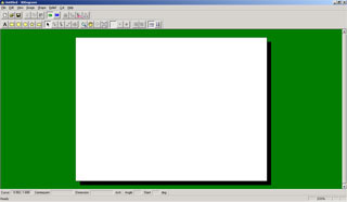
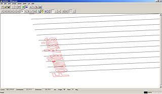
Orient your text in the bottom-left corner and invoke Properties (Alt+Enter) to alter the angle
Because the text will be 'projected' around the inside of a cylinder in real life, you can alter the scale of the text to choose how many degrees it will occupy. Use this formula:
For example, in the above screenshot, the text string is 19.76mm and will be cut on a Model-15 rotary with about 3000 steps/revolution. Using this formula, the text would occupy about 95°. If we want our text to occupy one revolution, it would need to be 75mm wide, from:
For quick reference:
- Model-15 and Model-20 rotaries are ~3000 steps per revolution,
- Model-15HR rotaries are ~4000 steps per revolution, and
- Model-20HR rotaries are ~6000 steps per revolution.
Also note text engraved on the inside of a rotating ring will read in the opposite direction. You must mirror it in software (right-click, MIRROR) or by using the Mirror switch on your Fourth Axis rotary.
Right click on your text and CREATE 3D ENGRAVING PATH
Check 'Engraving' and choose an appropriate depth
Confirm in the 3D view that the toolpath exists in red
Open CUT > LAYOUT and set your MARGIN to zero.
Now we can start up the MDX. If you want to guarantee a fresh start, follow these steps:
- run ClearPrintQueue.bat from your Fourth Axis installation,
- turn ON your MDX in XYZ mode and wait for it to finish moving
- hold down the UP/DOWN buttons simultaneously to clear the buffer
- when the lights stop flashing, UNVIEW your MDX and it will move to 0,0
Approach the face of the wax using the Layout dialogue
Now from the CUT > LAYOUT dialogue you can experiment with a tool fitted to find the top center edge point of the ring mounted in the rotary axis.
Move the tool by double-clicking the round target (or the button in the 'Cursor' frame). In conjunction with the UP/DOWN buttons on the MDX, you can record the correct Y position that corresponds to the ring axis. Save this for later reference, it is your Y-setback distance
Toggle your interface box to X-Rotary-Z mode.
If you have test wax mounted, you will want to experiment at least 5mm away in X until you understand where the tool will go on command. The trick with inside-ring engraving with the Roland software is ensuring a smooth entry and exit from the work area.
The tool must not descend from Zup before the cut, nor ascend to Zup afterwards, because the ring is in the way! We will need to make some tweaks to the RML-1 code generated by Roland 3D engrave.
Since you have 'explored' the work area with the cursor to find your Y-setback, you may now choose an artificially large X-offset to place the artwork within the work area. We used a 'Lower Left X' value of 55 when 'cutting some air' next to the wax, to watch the entry and exit of the tool.
Observe how the UP/DOWN buttons on the MDX define the height at which the MDX cuts the text. You need to set the height somewhere inside the ring, so it can go to the first point on the engraving without collision.
If you incrementally lower the X-offset, then instruct the MDX to 'cut air', you can observe the entry and exit movement by the tool. We will need to make alterations to the cut file, because Roland 3D Engrave has no idea that its output is curled up inside a ring!
To alter the data going to the MDX, we can set up the driver to save to a file instead of spooling directly to the machine. Here's how to get Roland 3D engrave to output to file:
Open up the PROPERTIES dialogue of your MDX-20 printer driver
From PORTS, note your current port and change the output to FILE
Now when you use the CUT command from Roland 3D Engrave, instead of the MDX moving and cutting air, you will be prompted where to save the file. Save it as "C:\inspect.plt" for later.
Start windows NOTEPAD (Start > Programs > Accessories > Notepad).
When you look inside the file for the machine co-ordinates, they are grouped in the commands "Zx,y,z". When you see negative numbers in Z, the machine is cutting wax - and when Z = 2420, the machine is raising the tool out of the work area. 2420 / 40 = 60.5mm, which is the maximum Z-travel.
Open up 'C:\inspect.plt' and take a look at the commands in the file. You can add carriage returns (ENTER) after the semicolons (;) to make the code easier to read. In the first few lines, you will see:
^IN;                (initialize machine with fresh settings)

^PR;                (change the movement mode to relative co-ordinates)
Z0,0,2420;          (move the Z-axis up to its 60.5mm maximum)

^PA;                (change the movement mode to absolute co-ordinates)

Z2600,2240,2420;    (move the tool to directly above the engraving)
Z2600,2240,40;      (descend to 1mm above the engraving surface)
Z2600,2240,2420;    (ascend back above the engraving)
You need to delete the red lines of code, to prevent the tool colliding on entry.
Now look at the end of the cut file. Again, add carriage returns (ENTER) after the semicolons (;) to make the code easier to read. You will see:
V15.0;              (change the movement speed to maximum for rapid-traverse)
Z2341,3880,40;      (return to the starting point above the engraving)

^PR;                (change the movement mode to relative co-ordinates)
Z800,0,0;           (move tool 20mm RIGHT (+x) of its current location)

!MC0;               (turn off the spindle motor)
You need to add the green lines of code, to prevent the tool colliding on exit. Next time the machine raises the tool, this ensures it is well away from the ring.
To see how your newly edited cut-code performs, you need to send it to the MDX through the usual port. This can be done in a 'Command Prompt' window
From START > RUN, type 'cmd' and click OK
Now enter "type C:\inspect.plt > COMX", where COMX was the original port you recorded earlier
Inside ring engraving using the Tilt Motor Mount
Press ENTER to send the file to your MDX, and observe how it moves the tool from the current position (wherever you left it with the UP/DOWN arrows), to inside the ring. Observe also how, immediately after finishing, it moves the tool 20mm away from the ring, safe for next time.
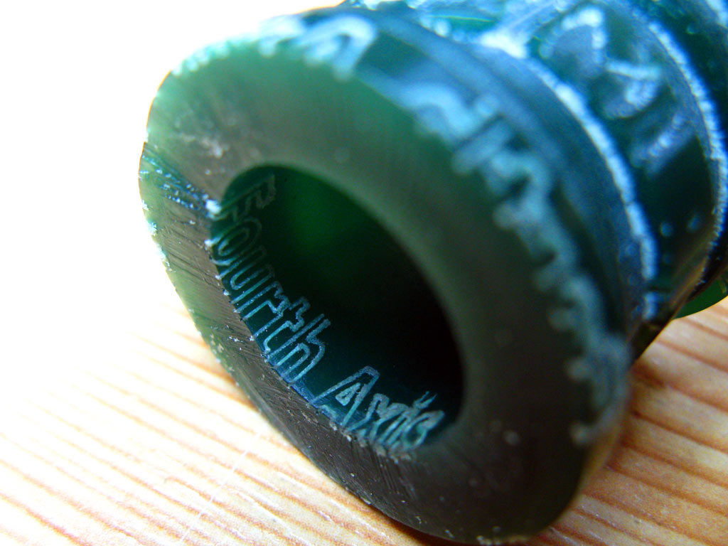
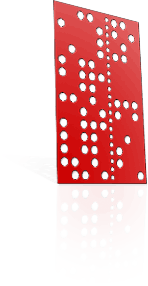
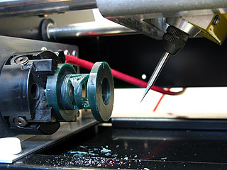
Engraving detail on a wax ring
You will need to take care 'cutting air' without tool, then 'cutting air' with a tool, after which you may be confident to take the next step to cut wax.
When you want to resume normal engraving, you may reset your driver to talk directly to the MDX again. Open up the printer properties again.
To restore normal output, select COMX (your original port)