Rotary MILLING using your Fourth Axis
In this section, we reproduce the scanned target!
Following on from the Rotary SCANNING tutorial, we rotary-mill a wax model of a drill bit in this tutorial. The source for the object can come from Modela Player 4, so we can use FARM for this particular workflow.
At this point, it is strongly recommended that you have read and understood most of the related philosophy in these four other tutorial sections:
- Rotary scanning tutorial with Dr Picza
- Picza-to-Rhino conversion tutorial
- Rotary data in Rhino (representing your model) tutorial
- Rhino-to-Modela conversion tutorial
- Open your .MPJ project file in Modela Player 4, to bring up the artwork you want to mill.
- You need to prepare the model for the generation of toolpaths in the correct axes. Start by choosing 'File > Select Machine', and ensuring that you have selected the MDX-40 model with the ZCL-40 rotary axis unit.
Now in the Modela Player 4 main screen, click the 'Model' button
 .
.Look in the "Size and orientation" tab. In the "orientation" preview pane that appears, you will want to orient your model so that it lies along the X-axis. The imaginary rotating shaft around which the object spins should be parallel to the red "X" axis ray in the preview pane. You may need to rotate your model around the Z axis to acheieve this.
Now look in the "Origin" tab. Check that you are comfortable that the green origin is where your axis / center of rotation would be. It is most convenient to set the X-axis origin to lie against the left edge of the model. Select this.
Back in the main screen, now click the 'Modeling Form' button
 .
.Look in the "Margin" tab. You may want to choose a margin of a few millimeters to the left and right (in the X-axis) of your object (especially if you plan to part-off or saw a segment free).
- Back in the main screen, choose your material (in this case Modeling Wax).
-
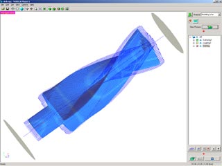
Surfacing, roughing, and finishing toolpaths are generated in MP4.Click the "New Process" button
 , and we can start generating our toolpaths.
Make processes as appropriate for surfacing, roughing and finishing, making sure to choose appropriate parameters that correspond to the wax blank that will be in your machine. You can use any axial/circumferential, scanlines/unidirectional settings you desire; FARM supports all modes.
As you create each process, you can create a toolpath "Right Now". By now you should have three processes visible in the right process-tree pane, and blue toolpath traces visible over the object displayed in 3D.
- When you are satisfied with all your toolpaths, click the "Cut" button. Make sure you tick "Output to file" and save each process; you will need the files for FARM to cut the ring in the next step! Sending the files directly to the machine at this stage will bypass our FARM emulation process, and your work will not be cut correctly.
Start your FARM software, and make sure you have entered the calibration number for your rotary.
Although your Fourth Axis is individually factory calibrated, the specified center height and Y-setback location are only nominal values which depend on various manufacturing tolerances of the host machine. Calibration procedures are described in a separate document included with FARM. It is necessary to follow the calibration procedures to achieve the best alignment between each of the cutting processes. When you do perform calibration, make a note of the center height and Y-setback location values. The calibration procedure only needs to be performed once for the life of the machine.
-
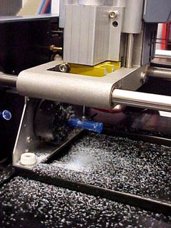
Your milling operations will commence as you work through FARM.FARM is a wizard type application which will guide you through loading and cutting the processes you created in Modela Player 4. When you press the 'Cut' button, FARM will automatically determine when it is necessary to attach or reorient the wax, or even when to change the interface box switch positions, and you will be prompted accordingly for each of these steps.
Please follow the instructions carefully and don't change the switch positions or click 'OK' in the dialogues prematurely, because this may result in loss of machine registration.
Between each process, the work is presented to the front of the machine for inspection or reorientation, and you will be given the option to change the tool before each cutting process at your convenience.
-
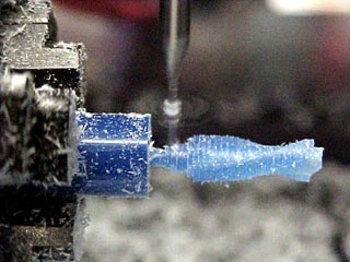
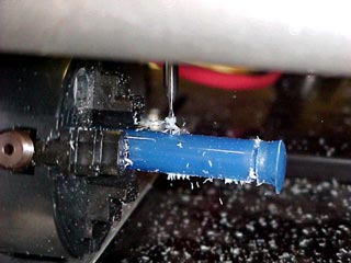
As the roughing pass advances, the helical shape is revealed.Execute the surfacing, roughing and finishing processes as instructed within FARM. Here, the profile of our example scan target becomes visible.
Sit back and enjoy your '3D photocopier'!
This concludes a five-part series of tutorials illustrating a possible Fourth Axis workflow.